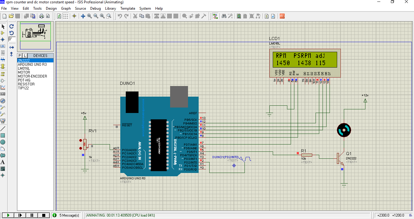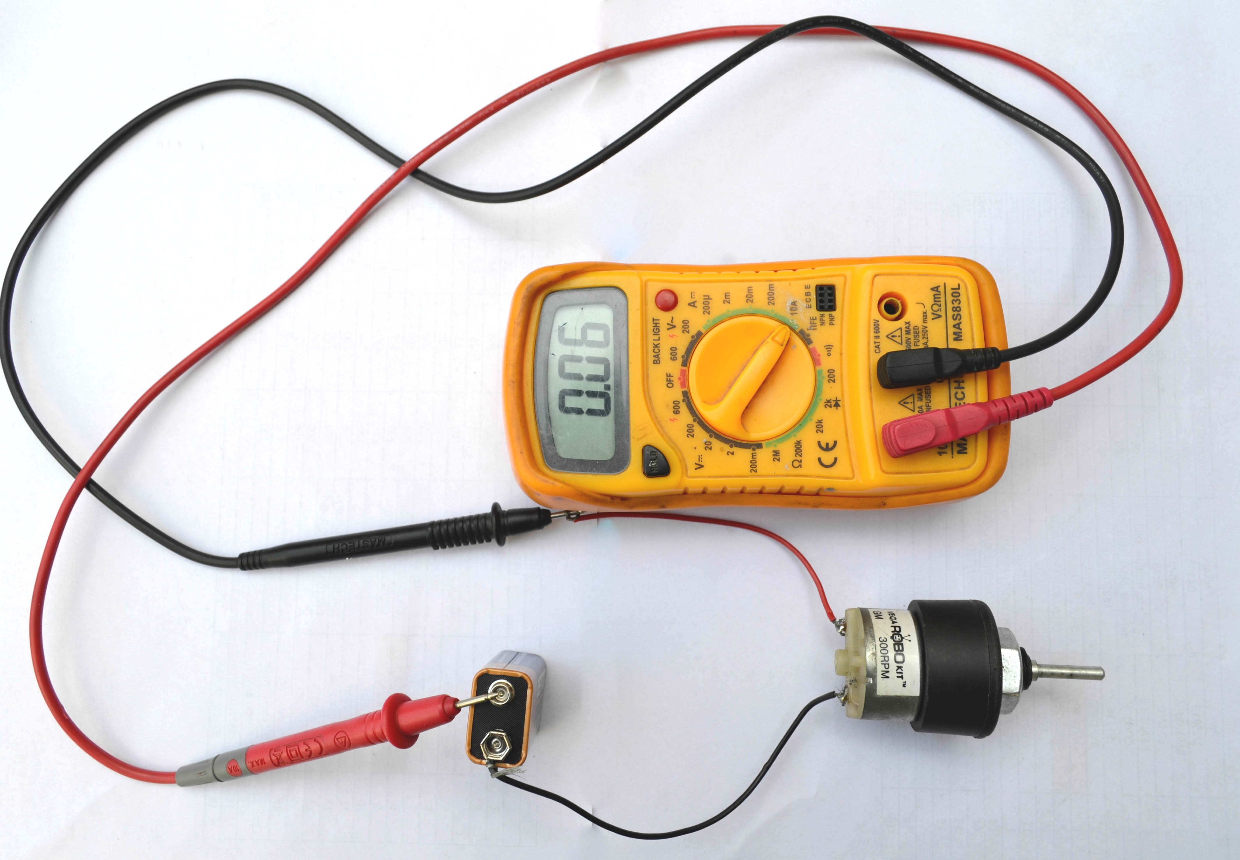
I will use 3 waveforms for this. For brushescommutator your best check is visual.

Connect the probes in the circuit according to the polarity.
How to test dc motor using multimeter. How to check a DC drive motor from a treadmill using a multimeter - YouTube. Steps for measuring dc voltage with a digital multimeter. Then insert the red probes into the V Ω jack.
When finished remove the probes in reverse order. Red first then black. Connect the test probes to the circuit.
Black to the negative polarity test point circuit ground red to positive test point. Connect the testing leads to the multimeter. Turn the knob to the DV voltage segment in the multimeter at 40DCV.
Connect the probes in the circuit according to the polarity. Image of multimeter showing DC voltage reading from LED circuit. Power on the Multimeter.
Note down the reading. Using your multimeter test the resistance between the motor frame and the earth. The readings of a good motor should not be more than 05 Ohms.
Otherwise any reading more than 05Ohms shows that your motor is faulty. You can check your continuity with an ohm meter. For brushescommutator your best check is visual.
A high speed or heavy duty motor can see problems where the rotor conductors are crimped into the comm segments. If the motor is dissasembled and you have a growler available you can test for shorts within the windings. To test your DC motor touch the leads of the ohmmeter to the leads of the motor.
The meters screen should indicate a low resistance somewhere between 10 and 30 ohms but if it reads an infinite ohms or an open circuit you should rotate the end shaft of the motor. Test the fourth set of wires. Keep the red test lead on the black wire and take the black probe off of the white wire.
Place the black probe on the white wire. It is preferable to do this test without the moving blade. The multimeter should show values around twenty ohms.
How to test DC Motor LED Resistor Capacitor Transistor with Digital Multimeter HindiMr Electron English. How to measure DCAC AMPS using a multimeter Current - YouTube. By following the following steps you will be able to measure DC amps with a digital multimeter at ease.
The first step is turning on the meter. When testing for continuity a multimeter beeps based on the resistance of the component being tested. That resistance is determined by the range setting of the multimeter.
If the range is set to 4000 Ω a multimeter typically beeps if the component has a resistance of 40 Ω or less. Place the copper sensors running from the multimeter onto the metal terminals on the small electric motor. The sensor on the end of the red wire from the multimeter touches the terminal that has a red wire attached.
The sensor on the end of the black wire from the meter touches the terminal that has a black wire attached. When testing VFDs use the low-pass filter setting in the advanced multimeters for accurate readings. For multimeters without the low pass filter setting turn the dial to dc voltage then press the Hz button again to measure the frequency on the dc voltage setting.
In DC a multimeter will not use RMS circuit but a averaging circuit. I will use 3 waveforms for this. A 50 duty cycle waveform from 0V to 10V this means the average voltage is 500V a RMS meter will show 500V It removes the DC component and the DCAC voltage is 707V because it is a square it will contain much higher frequencies than.